


Why Bosch LSU wide-band air/fuel ratio (or Lambda) sensors fail so often in aftermarket performance applications
Bosch is the world’s leading manufacturer of exhaust gas oxygen sensors. Their LSU range of wide-band sensors has been widely adopted by the OEMs and can be found on a huge number of production vehicles to accurately measure Lambda or the air/fuel ratio (AFR) in the exhaust system. Their common use as a mass-produced part has driven the cost of these sensors down significantly over the years and they have become very popular in the after-market performance tuning industry. We also, know that these sensors live in the harshest environment of all automotive sensors, but even so they have been designed with this in mind. On production vehicles it is common for these sensors to last for over well over 100,000kms. Yet in aftermarket performance installations it isn’t uncommon to hear of LSU sensors lasting for much shorter periods of time and in some cases failing very quickly. This article attempts to explain why this is. We’ll do this without getting into complex explanations of how these sensors work and all of the concepts discussed will be pretty easy for anyone to grasp. However, it isn’t a short article, so if you don’t feel like reading the whole thing then feel free to jump to the bullet points at the end. Once you understand how to avoid the common mistakes you should be able to get much better life out of these sensors.
What they look like on the inside
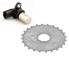
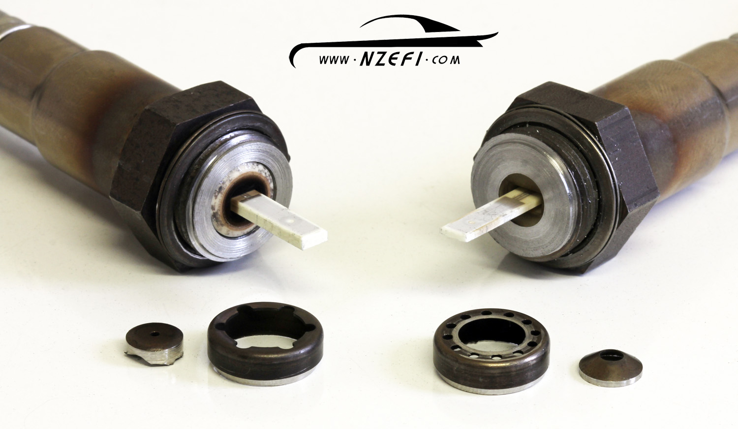
All Bosch LSU sensors we have seen have two protective tubes which cover the internal sensing element. These are designed as a passage to allow exhaust gas to reach and pass over the sensing element as quickly as possible while trying to block contaminants and water droplets that could damage the sensor (more on that later). If you remove the outer protective tube then the inner protective tube becomes visible as shown below. This has been redesigned significantly between the earlier LSU4.2 sensors and the later LSU4.9. Supposedly, the revised design of the protective tubes on LSU4.9 allows faster and more turbulent flow of exhaust gas through the sensor resulting is faster response times.
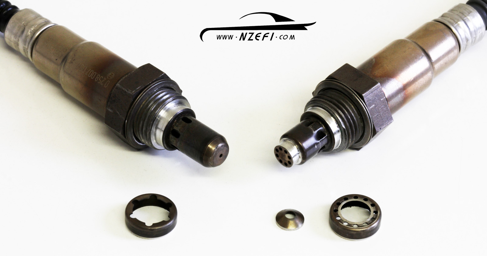
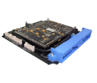
Remove the inner tube and you’ll reach the sensing element. This is effectively a little printed circuit board, but instead of being fibreglass based (which wouldn’t handle the heat), it is ceramic based. Instead of having a bunch of components stuck to the top and bottom like a conventional circuit board (which also wouldn’t handle the heat) everything is built into the board as it is constructed in additive layers somewhat like a common 3D printer. This process is known as thick-film technology and the end result is you effectively end up with a small electrical circuit that can survive in very high temperature environments like inside an exhaust system. Looking at the complete sensing element you can’t easily see the circuit tracks or its components – it just looks like a thin wafer of ceramic material with all the clever stuff hidden on the inside. The entire sensing element on the earlier LSU4.2 sensors was approx 2mm thick and on the later LSU4.9 sensors the sensing element thickness shrunk down to approx 1mm thick as shown in the pictures below. The later thinner sensing element may contribute to the faster response times of the LSU4.9, but it is likely to be more sensitive to vibration and mechanical shock.
The ceramic sensing element consists of both a sensing circuit and a heater circuit. The sensing circuit should ideally be kept at a constant temperature of 780 degrees C, which is where the heater comes into play. While, the exhaust gas temperature (EGT) by itself will do part of the job to heat the sensor, the heater power must be carefully controlled in order to bring the sensing circuit up to exactly the required temperature and then keep it as close as possible to that target temperature. For example, when the EGT rises due to increased engine load and speed, clearly the heater power needs to be progressively decreased. Eventually at high enough engine speed and load the heating circuit will be turned off completely. And if the EGT continues to heat the sensing element beyond 780 degrees C then the controller can’t do anything to reduce it.
During engine starting the sensing circuit cannot be activated until it has reached at least 600 degrees C. Therefore, ideally you want to get it up to temperature as soon as possible. However, fast temperature changes in the sensing element (either heating or cooling) will cause it to fracture and fail so that prevents the heater being turned on at full power straight away. But there is another very good reason why in most cases, the heater circuit power must stay reduced for an even longer period of time . That all comes down to condensation that has formed on the inside of the exhaust system during the last time the exhaust cooled down.
Thermal shock – a leading cause of failure
You may have noticed that when you start a cold engine, quite a lot of water will come out of the exhaust system as the engine warms up. Sometimes it is just a light mist, but in other cases drips or even a trickle can be observed particularly if you rev the engine when it is cold. This is the result of moisture that has condensed on the inside of the exhaust being blown out and/or evaporating. Bosch is well aware of this phenomenon and their LSU sensor technical documents are littered with comments about it and what do to about it. Remember that the sensing element can’t be heated or cooled too quickly or it will fail? Well if your sensor is heated up to full temperature before starting a cold engine then those cold droplets of condensation will hit the hot sensor and destroy it very quickly – this is commonly referred to as thermal shock. As a result Bosch thoroughly points out that the sensor heating must only start after the engine is running and even then the heater power should be limited to about 15% of its full value until condensed water is sure to be gone. Only then should high-powered rapid-heating of the sensor occur. The following comments come directly from Bosch:
“In the warm-up phase at engine start, the sensor is operated with reduced heater power..……. The heater power must only be increased when the presence of condensed water in the exhaust gas system can be ruled out.”
“The sensor ceramic element is heated up quickly after heater start. Prior to heating up the ceramic element, it must be guaranteed that there is no condensed water present. This could damage the hot ceramic element.”
“Never switch on sensor heating or the control unit before engine start.”
“….. the sensor installation location design must be selected in a way to minimize, or eliminate, condensed water on the exhaust gas side from contacting the sensor. If this is not possible by design measures, the start of the sensor heater must be delayed until demonstrably no more condensation water appears.”
We could go on an on listing more similar quotes from Bosch, but you probably get the point by now. It’s pretty clear – never let cold droplets of condensation hit your fully warmed up wideband sensor. But that is exactly what often happens in so many installations using after-market air/fuel ratio or lambda controllers designed specifically to work with these sensors.
Limitations of many aftermarket controllers
Most cars that have a wide-band Lambda sensor as a factory fitted part will have their Lambda sensor controlled directly by the engine control unit (ECU). This means that the sensor’s controller knows exactly when the engine is running. Additionally, on a production vehicle where every sensor is installed in the same place, the ECU has the ability to calculate how long it will take for condensation upstream of the sensor to be cleared after a cold start.
In contrast, most stand-alone aftermarket wide-band Lambda sensor controllers have the Lambda sensor itself as their only input. Without engine speed information, they generally assume that the engine is started as soon as the ignition is turned on and the controller is powered. Also, if the sensor is mounted at a position in the exhaust further away from the engine then most stand-alone controllers have no way of knowing this. Therefore, during a cold start, the delay time until high powered heating occurs will not be increased.
Misleading Information
Bosch also tells us the following:
“The sensor must not stay in the exhaust gas stream when it is not heated or when the control unit is switched off.”
Most manufacturer’s of aftermarket wide-band Lambda controllers, pass this point on in their instruction manual in one form or another. It is indeed true that leaving a sensor in the exhaust system without it hooked up to a fully functional controller will kill the sensor. However, doing this for a couple of seconds isn’t a problem. In talking with many of our customers who are the end user’s of aftermarket wide-band controllers, we have often found that many interpret this piece of information to mean that the sensor needs to be fully heated up BEFORE starting the car. In reality nothing could be further from the truth. It isn’t a co-incidence that these customers are the same ones that are killing sensors frequently. After having a brief chat with them and setting them straight their ongoing sensor problems often disappear.
Our recommendation
To get the best life out of your wide-band lambda sensors, we recommend the following:
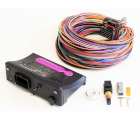
- Consider using a controller that is either integrated into an ECU or one that receives an engine speed input via a wired input or over CAN bus. Options meeting this criteria include the Link G4+ Fury, G4+ Thunder, or using Link’s external CAN-Lambda controller with a suitable ECU.
- If using a stand-alone controller without an engine speed input, never let your controller heat the sensor prior to starting the engine. One way to guarantee this is to power the controller off of its own relay which is not turned on until after the engine is started.
- Place your sensor less than 1m from the engine in a position upstream of any parts of the exhaust system where condensation is likely to pool or settle. In high exhaust gas temperature applications, consider using a longer heat-sink type sensor boss rather than moving the sensor further from the engine.
Other factors
While we think that thermal shock (as described in this article) is a leading factor that kills wide-band Lambda sensors in aftermarket installations, it isn’t the only factor. Other more commonly known factors include:
- Mechanical shock – remember that 1mm thick ceramic wafer on a LSU4.9? It wont handle excessive vibration, being dropped or the exhaust system it is fitted to making contact with the ground (ripple strips etc).
- Contamination – Oil burnt as part of the combustion process (worn out four stroke, or any two-stroke or rotary applications) or worn out turbo seal rings will reduce the life expectancy of a sensor. Particulates from an excessively rich tune, lead from leaded fuels, anti-freeze from a blown head gasket or excessively applied silicone sealant are other possible contamination sources.
- Excessive EGT – While LSU4.9 sensors are actually rated to be able to withstand exhaust gas temperatures as high as 980 degrees C, if the sensing element goes too far above the controlled target temperature, then many aftermarket controllers will enter a fault mode. In the fault mode the controller may stop controlling the sensor which is effectively like not having the controller turned on at all while the sensor is fitted to the exhaust. Therefore continuing to drive while the controller is in a fault mode can kill a sensor that would otherwise be fine. Resetting the controller to get it out of fault mode can typically be done simply by turning the controller off and back on again.
Conclusion
We hope that the information provided in this article will help save many wideband AFR/Lambda sensors from an untimely death as well as saving our customer’s the aggravation and cost of having to replace their sensors more frequently than necessary.
Read More »